Chapter 00
The Circuit
In which a battery, a resistor and a small red light become a circuit — and three words arrive that will carry the rest of the season.
1A loop, and nothing else
Take a 9-volt battery in one hand and look at its top. There are two snaps: a small round one and a larger hexagonal one. Touch nothing to them and nothing happens. The battery is ready to push, but there is nowhere for anything to go.
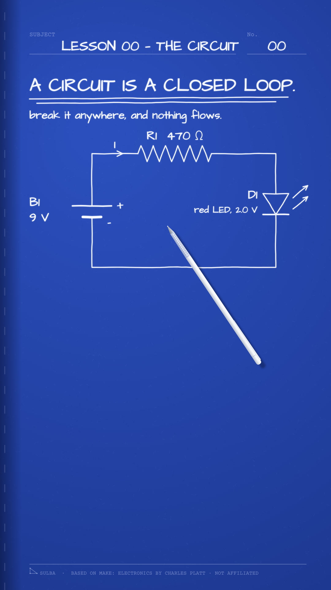
Now picture a path that leaves one terminal, runs through a few parts, and comes back to the other. That closed path is a circuit, and it is the only arrangement in which a steady current can flow. Break it anywhere — lift a single wire — and the current stops everywhere along it, all at once. There is no such thing as half a circuit.
Our first one has three parts: the battery, a 470-ohm resistor, and a red light-emitting diode — an LED. It is about as small as a useful circuit can be, and by the end of this chapter you will be able to say exactly how much current flows round it, and why.
2Three words
Before any arithmetic, three words. You will meet them in every chapter that follows, so it is worth getting them straight now.
Voltage is the push. It is measured in volts, written V. The battery's label says 9 V; an ordinary AA cell says 1.5 V, so this battery pushes 6 times as hard.
Current is the flow: how much electric charge passes a point in the circuit each second. It is measured in amperes — amps, for short — written A. The currents in this book are small, so we will often use the milliamp, mA, which is one thousandth of an amp.
Resistance is what stands in the way. A part with more resistance lets less current through for the same push. It is measured in ohms, written with the Greek letter omega, Ω.
One convention to settle before we go on. On a diagram, current is drawn leaving the battery's + terminal and returning to its −. That direction was agreed long before anyone knew what was moving; in a copper wire the charges that move are electrons, and they drift the other way. The arithmetic does not mind, and neither will we, as long as we stay consistent.
3Ohm's law
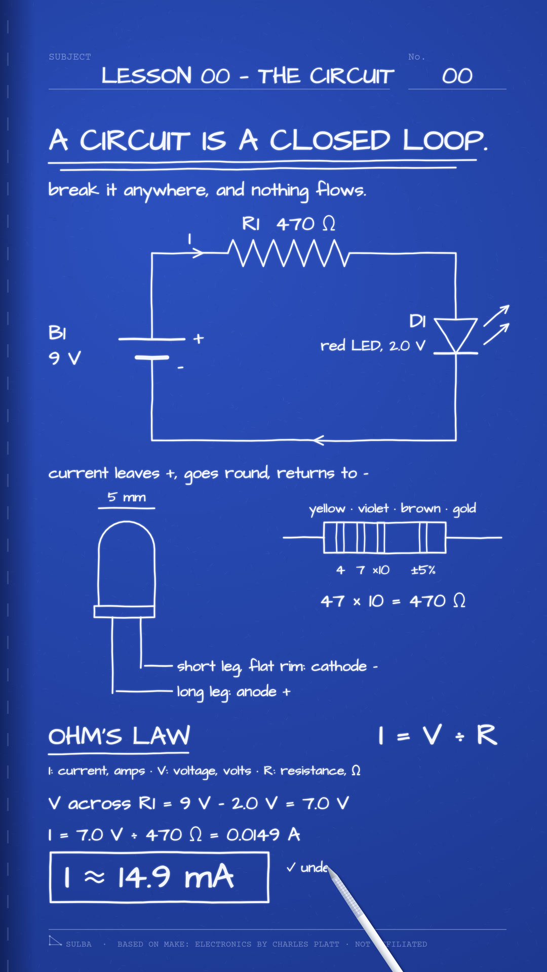
The three words are tied together by one rule, named after Georg Ohm, who published it in 1827. In words: the current through a part equals the voltage across it, divided by its resistance.
To use it, we need the voltage across the resistor — and that is not the whole 9 volts. An LED does not light until there is a certain voltage across it, its forward voltage, and for a red LED about 2.0 V is typical. Whatever the LED takes, the resistor gets the rest:
Now Ohm's law gives the current:
Two honest caveats. The figure assumes the battery is exactly 9 volts and the LED exactly 2.0; a fresh battery reads a little above its label and sags as it is used, and no two LEDs are quite alike. A meter on a real circuit will read close to 14.9 milliamps, not precisely it. That is normal, and you will learn to expect it.
4Why the resistor is there
It is tempting to leave the resistor out. Don't. An LED is not a resistor; it is a diode, and it behaves very differently. Below its forward voltage almost no current flows. Just above it, the current climbs steeply for every extra fraction of a volt. Connect an LED straight across a 9-volt battery and nothing limits that climb: the LED is destroyed.
The resistor is what sets the current. A typical 5 mm LED is rated for about 20 milliamps continuously, so we can ask which resistor would give exactly that:
Any larger resistor gives a smaller current and a slightly dimmer, longer-lived LED. With 470 ohms we get the 14.9 milliamps we worked out, comfortably inside the rating.
5Reading the resistor
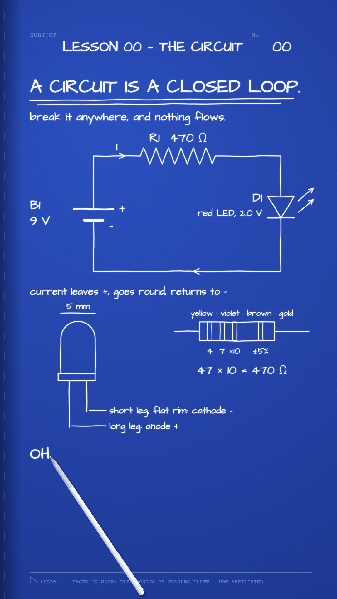
A small through-hole resistor carries its value as coloured bands. Hold it with the gold or silver band on your right and read from the left. On a four-band resistor the first two bands are digits, the third tells you how many times to multiply by ten, and the fourth — the tolerance — says how far the real value may stray from the marked one.
5 per cent of 470 is 23.5, so this resistor may measure anywhere from 446.5 to 493.5 ohms and still be true to its marking.
6Which way round
A resistor works either way round. An LED does not: it lets current through in one direction only. Its longer leg is the anode, and it goes towards the battery's +. The shorter leg, on the side where the LED's rim has a small flat edge, is the cathode, and it goes towards −.
The battery is marked the same way, if you know where to look: on a 9-volt battery the small round snap is + and the larger hexagonal one is −.
7Where the energy goes
Power is the rate at which a part takes energy from the circuit, measured in watts, W. A resistor turns all of it into heat, and its power is the current multiplied by itself and then by the resistance:
The small resistors you are likely to buy are rated for a quarter of a watt, 0.25 W, so this one is working at about 42 per cent of its limit. It will feel faintly warm, if at all.
The LED takes its voltage multiplied by the current:
That is milliwatts, thousandths of a watt. Only part of it leaves as light; the rest gently warms the LED. Add the two together and you have exactly what the battery supplies — 9 V × 0.0149 A = 0.134 W. Every bit of it is accounted for, as heat and as light.
8Round the loop
One more rule, named after Gustav Kirchhoff, who set it out in 1845. Go round any closed loop and the voltages across the parts add up to the voltage of the source:
We used it already, quietly, when we said the resistor gets whatever the LED leaves. It is also how you check a circuit with a meter: measure across each part in turn, and the readings should add up to the battery's.
9Build it
You need a 9-volt battery and a snap for it, a 470-ohm resistor rated 0.25 W, a red 5 mm LED, a small breadboard, and two jumper wires.
A breadboard is a block of holes. Under each short row of five holes runs a metal strip, so anything pushed into the same row is joined. Push the resistor's legs into two different rows. Put the LED's long leg in the row with the resistor's second leg, and its short leg in a row of its own. Run one wire from the battery's + to the resistor's first row, and another from the LED's short-leg row to −.
The LED lights. Now pull either wire. The light goes out at once, because the loop is open — which is exactly where this chapter began.
In the next chapter we take the first of the three words on its own: what a volt is, and why a battery has one.
Based on Make: Electronics by Charles Platt · not affiliated.